Description
Introduction
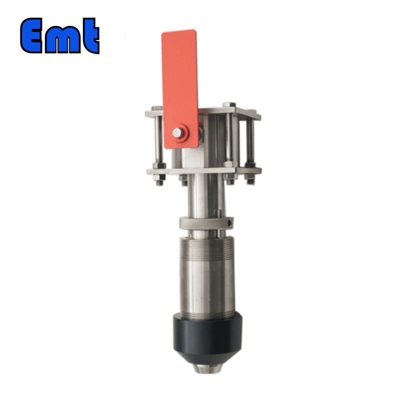
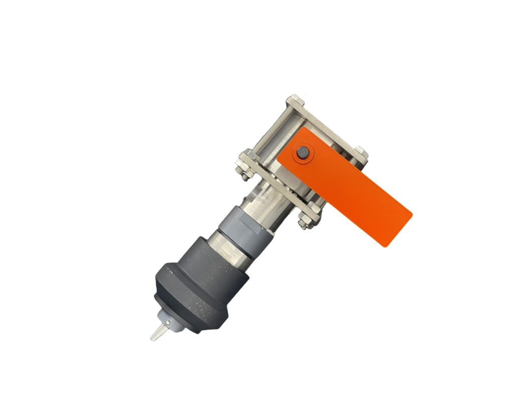
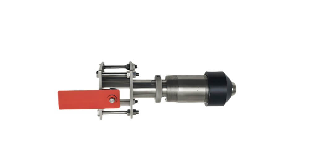
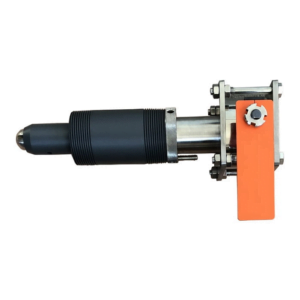
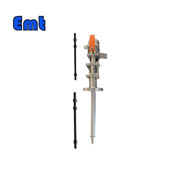
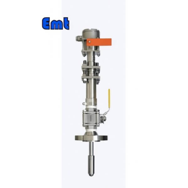
The Pipeline Engineering Pig Signaller is a non-electrical, explosion-proof device designed for efficient pipeline monitoring, offering adjustable probing depth and reliable signaling of pig passage. Its easy installation, inspection, and maintenance make it a versatile tool for various pipeline thicknesses.
Characteristics of the Pipeline Engineering Pig Signaller
- A and B are intrinsically explosion-proof (they are non-electrical and hence not “intrinsically safe explosion-proof electrical devices”). This pipeline pig signaler has no electrical components, and there is no friction or collision between metals.
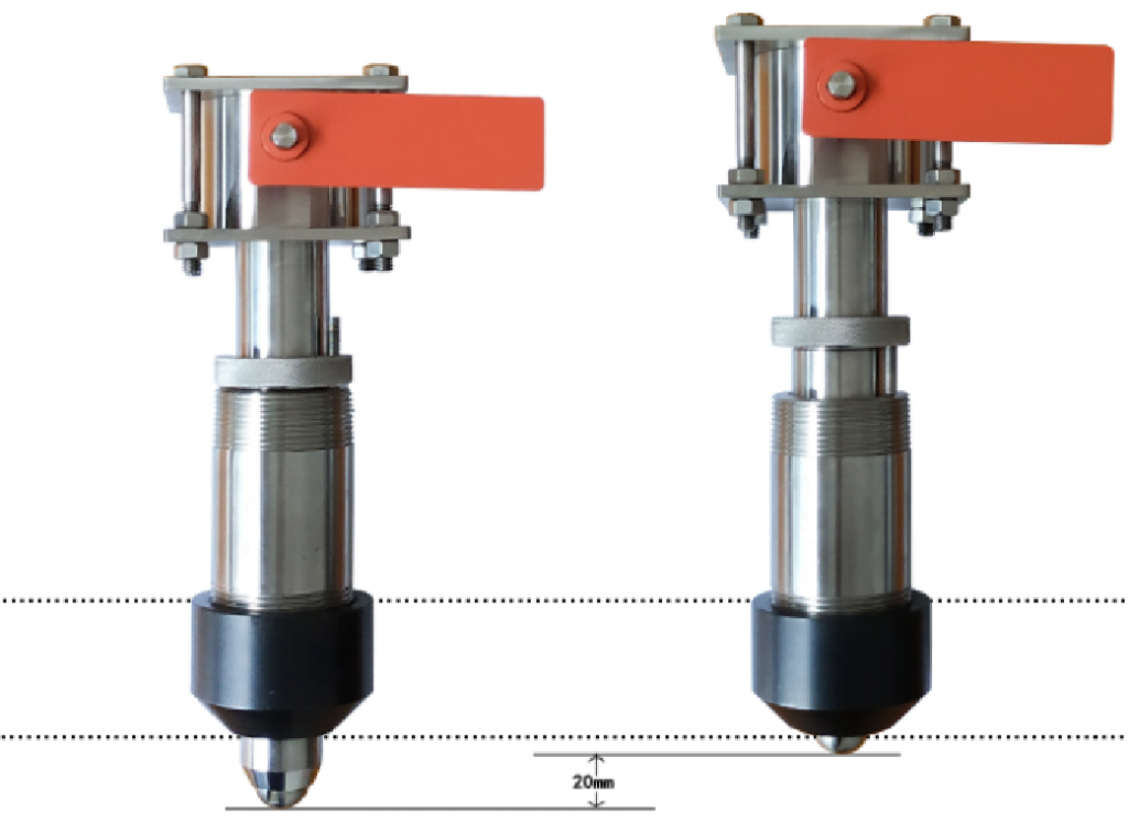
- Adapts to a wide range of pipe wall thicknesses. The probing depth of the pin of this pipeline pig signaller is designed to be adjustable, with a range of 0–10 mm, adjusted by 1 mm/step (half turn).
Main Technical Specifications of the Pipeline Engineering Pig Signaller
- Working pressure: 0–5 MPa and 0–16 MPa (or designed according to user requirements);
- Operating environment temperature: -20 to 120°C; (composite value may vary for specific media)
- Base material: Q235A or 20# (standard configuration)
Installation and Inspection of the Pipeline Engineering Pig Signaller
Firstly, determine the extension length of the pin. Adjust the extension length of the pin by rotating the movement according to the thickness of the pipeline wall. After installation, the spatial position of the pin’s axis should be between 0-3mm above the inner wall of the pipeline. Record the relative position b (the distance from the top of the movement display seat to the top of the base).
Then, complete the welding and installation process in four steps.
- Insert the pig signaller with the adjusted extension length into the opening of the pipeline. Rotate the movement so that the straight line formed by the flat mouth of the movement is parallel to the direction of the pipeline. Weld a point at the weld joint for positioning. When the step on the base cannot complete the insertion depth positioning by itself, manual positioning is required during welding.
- Unscrew the movement from the base and place it in a clean packaging box.
- According to the welding requirements (see Section 7, Welding Requirements), securely weld the base to the pipeline.
- After the base has cooled, apply lubricating oil to the sealing surface of the movement and the base, and reassemble the movement onto the base. The value of b should basically conform to the already recorded dimensions, and the straight line formed by the flat mouth is parallel to the direction of the pipeline. Then, tighten the locking nut to seal it externally and prevent the movement from rotating.
Sensitivity Inspection and Adjustment for Type A
The stainless steel cylinder installed on the sealing sleeve is removable. Its function is to protect and limit the position of the indicator flag. After the pig indicator has been installed, if you need to inspect whether the device is sensitive and reliable, you can remove the stainless steel cylinder and simulate the downward movement of the connecting rod.
During the process of unscrewing the stainless steel cylinder, the flag cap will pop up. By design, the maximum displacement that the pin can cause the connecting rod is 13mm (when the pin is actuated to produce a 90-degree deflection). The distance moved by the stainless steel cylinder when the flag cap pops up is the required displacement of the connecting rod.
You can increase the sensitivity of the pig indicator by rotating the stainless steel cylinder counterclockwise. However, be careful not to increase the sensitivity to the point where only a connecting rod displacement of ≤3mm is needed (the flag cap will pop up after the stainless steel cylinder is rotated counterclockwise two turns).
Before using the pig indicator below the freezing point, make sure that the flag cap of the instrument has not been frozen to the stainless steel cylinder. To do this, rotate the stainless steel cylinder counterclockwise. If the flag cap of the instrument can pop up, this means the instrument is working properly. If it cannot pop up, this indicates that the flag cap is stuck. You should separate it, wipe the contact surfaces dry, and then return it to its original position.
Adjustment of Display Direction for Types B and C
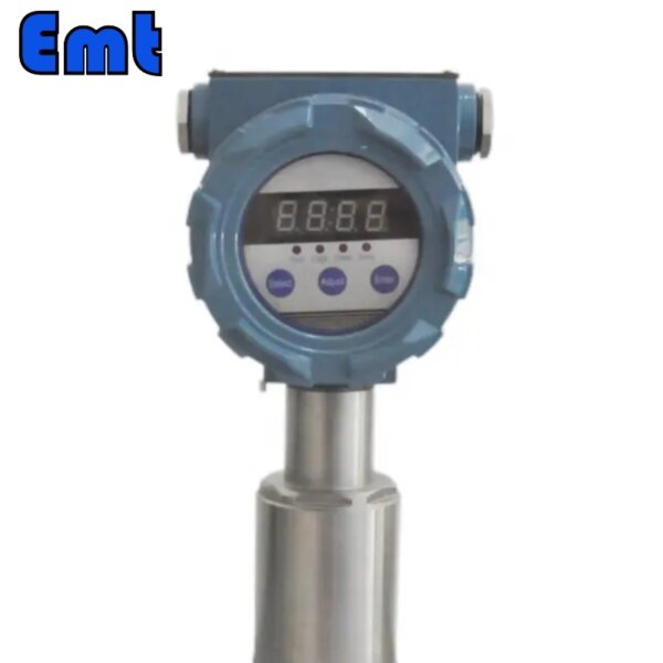
After completing the installation steps, if you need to adjust the direction of the display, you need to slightly loosen the four nuts under the display method orchid. Rotate the dial clockwise, and after reaching a suitable position, tighten the four nuts that were loosened.
Working Principle
The end of the movement installed on the base has a bi-directional trigger pin, which extends into the interior of the pipeline near the pipe wall. When the pipeline pig passes by, the pin is actuated, pulling the link rod and causing the flag indicator cap to pop up. Once the flag indicator cap pops up, it maintains a sprung-up state until manually reset, indicating that the pipeline pig has passed.
After the pipeline pig passes, the pin will automatically reset. At this point, forcibly pressing down the flag indicator cap can reset it, putting it into standby mode. If pressing the flag indicator cap does not reset it, it indicates that the pipeline pig is at this location, and the pin has not reset.
Maintenance
The non-metallic sealing ring between the base and the movement of the welded base flag indicator is used for sealing the pipeline medium. After one installation, its sealing surface will automatically match the sealing surface dimensions of the movement and the base. When it is necessary to disassemble the movement for off-site repair or replacement, use a small lever such as a flat-blade screwdriver. Insert the flat blade into the ring groove in the upper part of the sealing ring and carefully remove the non-metallic sealing ring. Label it (including the machine position, and time) for storage. Use it again when the original movement returns. When installing a new movement on the original base, a new seal ring should be used.
Once a new sealing ring has been used, it can be reused only when it is always followed by the movement that used it. In other words, a used sealing ring can be installed with the movement that is used on other compatible bases.
When a leak occurs at the sealing ring, first check if the lock nut is tightened. If it has been tightened, it is very likely that the sealing surface was not clean during installation, resulting in a loose seal. This situation requires reinstallation after the pipeline stops and depressurizes. Whether a new seal ring is needed depends on the situation during reinstallation.
If the Pipeline Engineering Pig Signaller has been contaminated by viscous materials, first remove the stainless steel cylinder, then disassemble all the components of the stainless steel cylinder for cleaning.


Reviews
There are no reviews yet.