 basa Jawa
Description
Description
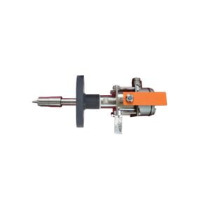
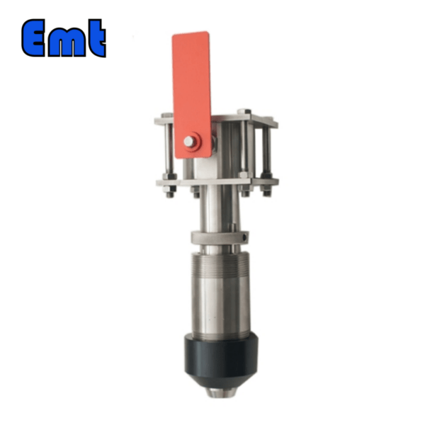
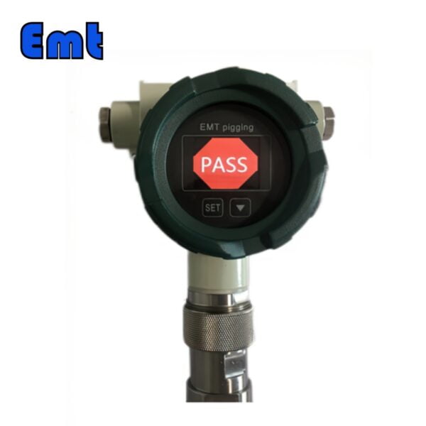
The mechanically operated intrusive pig indicator is a versatile device, typically featuring bi-directional functionality and mechanically operated signal flags. These flags can be manually reset and mounted on both vertical and horizontal pipelines. The flag’s default position is horizontal, indicating “pig not passed,” and vertical for the “pig passed” condition, with a manual latch reset to the horizontal position. As a pig moves through production pipework and pipelines, the signaler helps determine the pig’s location and timing, as well as estimate debris accumulation in front of the pig, enabling the identification of pipeline sections where debris buildup occurs.

General Function
A pig indicator is a device mounted on a pig transmitter and receiver stations to confirm the launch or arrival of a cleaning pig. Installed on pipelines, pig signalers detect the passage of all types of pipeline pigs. The flag interacts with the trigger mechanism, allowing for online flexibility checks of the trigger mechanism. Pig signalers are useful for determining if a pig has passed through the pipe during cleaning operations and can be easily installed via flange connections, available in various sizes to accommodate different pipe requirements.
Application
Pig indicators are essential for monitoring the passage of cleaning pigs in oil, gas, water, and other pipeline types.
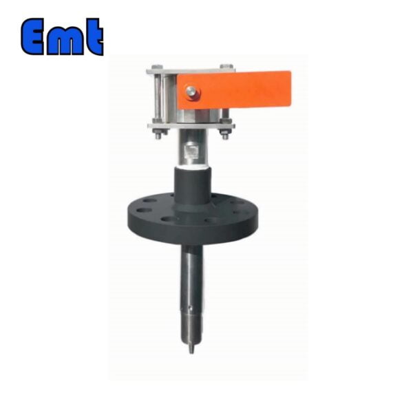
Pig Indicator with Manual Reset Flag (Flange connection)
Connection type: Flange connection
Types of pig indicator: Intrusive, Manual reset flag
Basic Features or Parameters
- Installing type: 2” Flange As per ASME B16.5 (CLASS150-2500)
- Plug body length: 200mm or as per customer requirement
- Insert depth (In pipe): 21mm
- Insert depth adjustment: Unadjustable
- Operating temperature: -20℃ to 120℃ or as per customer need
- NACE MR 0175: Yes
- Ingress Protection: IP66
- Remove under pressure: No
- Trigger type: Bi-directional or Uni-directional
- Internal part material: 316LSS
- Flange/Body material: PTFE Coated A105N or as per customer need
- The standard configuration of Uni-directional trigger shape: Ball shape
- The standard configuration of Bi-directional trigger shape: Firing pin shape
Drive Mode:
- Direct drive (Bi-directional trigger)
- Magnetic (Uni-directional trigger)
The direct drive mode offers better performance and is maintenance-free, while the magnetic mode allows for online checks. The trigger force in the magnetic mode is unaffected by pipe pressure, making it more sensitive under equal pressure compared to direct drive. However, over time, the uni-directional trigger may become blocked by grease or impurities, requiring cleaning and maintenance. In contrast, the bi-directional trigger is less susceptible to grease interference and requires no maintenance.
How does an intrusive pig indicator work?
The intrusive pig indicator is activated when a pig passes through the pipeline. It comprises a flag and a set of trigger devices, with the flag set horizontally to indicate that the pig has not yet passed. When the pig passes, the firing pin moves, pulling the connecting rod in the seal sleeve and causing the flag shaft to rotate 90° from horizontal to vertical due to the torsion spring action. This indicates that the pig has passed.
What is the Difference Between Intrusive and Non-intrusive Pig Indicators?
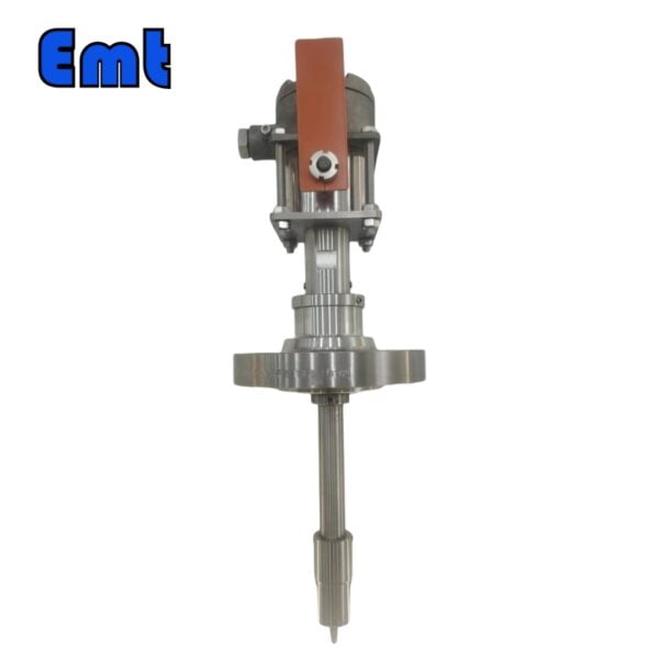
An intrusive pig signaler is inserted directly into the pipe, while a non-intrusive indicator is mounted externally. Intrusive indicators are typically mechanically attached to pipes, requiring a 2-inch branch connection or pipe opening. When these conditions are not met or the opening is inaccessible, a non-intrusive signaler may be used. Non-intrusive indicators can be installed anywhere on the pipe and are easier to install compared to intrusive indicators.
Flange Connection
Flange connections are widely used in pipeline connections, ensuring stability and sealing. The flange connection process involves the following steps:
- Preparation: Choose the appropriate flange and seal, check the flange surface for smoothness, and clean debris and grease from the flange and pipe end face surfaces.
- Install the flange: Align the flange with the pipe end face and secure it to the pipe using bolts. Ensure proper bolt tightening sequence and strength to prevent leakage.
- Install the gasket: Place the gasket between the flanges, ensuring it matches the flange in size and shape to avoid distortion or displacement during fastening.
- Fasten flanges: Use a wrench or torque wrench to tighten bolts individually, following a specific sequence and force until all bolts are fastened in place.
- Check for leaks: Inspect the connection for water or gas leaks and, if necessary, re-install the flange, replace the sealing gasket, and re-tighten the flange.
When installing flange connections, select appropriate flanges and sealing gaskets based on pipeline material, pressure, temperature, and other factors to ensure connection safety and reliability.
Main technical indicators
Main body working pressure: 0-15MPa(can design 0-26MPa)
Standard: 2″ ANSI 600# RF flange
300# 900# RF flange (or 1500# flange) can be configured according to the user’s needs.
Operating temperature: -20-100℃
Thrust length (the length from below the flange to the end of the extension sleeve — the distance from the top of the flange to the inner wall of the pipe): 150mm;
Interface: 1/2NPT;
Switch type: SPDT or DPDT Switch Capacity: 3A/24VDC

Installation Method
- Before installing the indicator, pre-install the flanges (flange specifications, grade, mounting hole distribution, etc., should conform to ANSI 16.5 or Custom standards) onto the pipe. Ensure a distance of 150mm or a custom size from the flange top to the pipe wall.
- Detach the display with the threaded nozzle from the flange base as illustrated below.
- Utilize a gasket suitable for the flange in use (when using an RF flange, the gasket thickness should be 3-5mm). Place the gasket between the two flanges, ensuring the indicator’s firing pin action direction aligns with the pipeline direction (i.e., the notch faces the pipeline direction). Insert the extension sleeve into the pipe and secure the flange base to the pipe joint using bolts.
- Wrap several layers of raw material tape around the thread of the display thread nozzle and tighten the thread until it reaches the limit position. Attach the docin.com tube to the flange base threaded interface. Be mindful of the screw nozzle’s depth limitation while screwing in the display.
Reviews
There are no reviews yet.