 basa Jawa
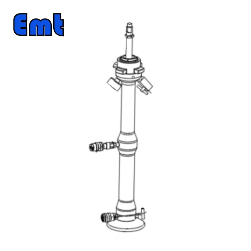
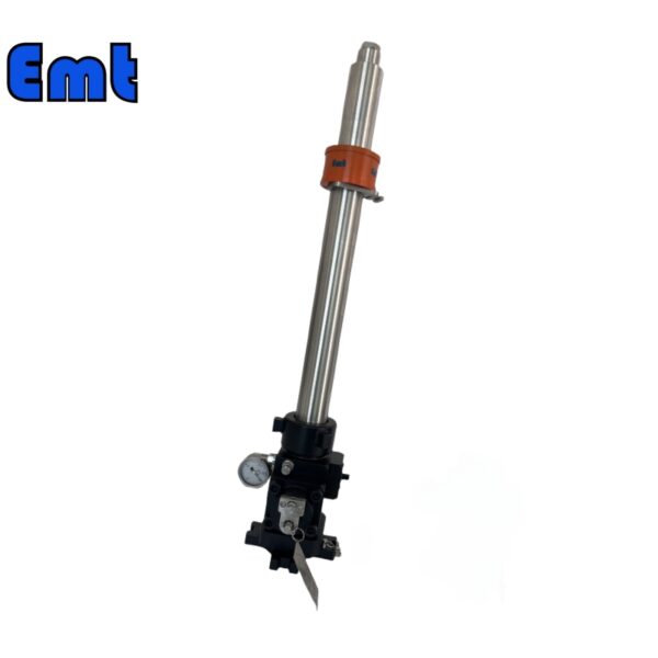
Description
The Hydraumatic Retriever Tool enables the exchange of corrosion monitoring equipment in a fully pressurized pipeline system, eliminating the need for pipeline closure or pressure reduction. To enhance safety, this tool is equipped with a Double Block and Bleed (DBB) valve, thereby extending its operational duration. Additionally, it can be operated using a manual hydraulic pump.
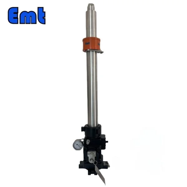
Specifications of the Tool
| Model | EMT-HRTV-000 |
| Maximum fetch and drop length | 400mm |
| Applicable pressure range | 0-6000Psi |
| Applicable temperature range | -6O℃-200℃ |
| Size | 176×176×1186 |
| Net weight | 30Kg |
Using Restrictions
When utilizing the tool, it is imperative for the operator to collaborate with a trained worker in order to assess safety concerns associated with the specialized positioning of the tool. A comprehensive evaluation must be conducted from inception to completion, taking into account potential hazards arising from the flow of gas or liquid. Particular attention should be given to the following aspects: determining whether debris within the pipes poses a risk of compromising the seal between the retriever and bleed valve (with consideration given to FVMQ as standard O-ring material); assessing if there are any potential dangers resulting from debris coming into contact with operators. If affirmative results emerge during this evaluation or if any other issues arise that cannot be effectively mitigated through safety precautions, the operation of the hydraulic retriever tool under fully pressurized conditions should not proceed.
The General Situation of the Hydraumatic Retriever Tool
Our company develops and produces hydraulic lifting tools for the safe and convenient installation or retrieval of corrosion hooks or corrosion probes in pipelines operating at normal working pressure.
Compared with the traditional mechanical design, the hydraulic design can greatly reduce the size and weight of the hydraulic tools, greatly improve portability, and reduce the space requirements of the product.
At the same time, through innovative design, the hydraulic take-and-place tool is driven by a manual hydraulic pump, which makes the operation more convenient and labor-saving, and the use of replaceable connectors greatly extends the service life of the tool.
Name of Parts
| Name | |
| 1 | Double isolation valve hammer nut |
| 2 | Double isolation valve operating handle |
| 3 | Hydraulic retriever tool hammer nut |
| 4 | Pressure gauge for hydraulic take-and-place tools |
| 5 | Hydraulic take-and-release tool drain valve |
| 6 | Hydraulic outlet quick connector |
| 7 | Hydraulic inlet quick connector |
| 8 | Hydraulic removal tool valve stem |
| 9 | Manual hydraulic pump assembly |
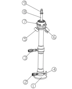
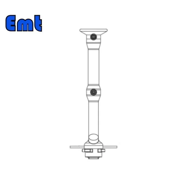
Figure 2
① Handwheel
② Hydraulic inlet quick connector
③ Hydraulic outlet quick connector
④ Cylinder head valve
⑤ Hydraulic pressure gauge for taking and placing tools
⑥ Hydraulic tools drain valve
⑦ Hydraulictaking and placing tools hammer nuts
⑧ Hydraulic take-and-place tool connecting rod
⑨ Connecting rod
Preparation And Inspection Before Installation
I. Take out the hydraulic retriever tool, manual hydraulic pump, and high-pressure hydraulic hose from the packing case, then put them to the ground carefully. Check if there is any surface damage. Rotate the ⑦ Hydraulictaking and place tools and hammer nuts in Figure 2. Make sure that it has a good running rotation, and does not affect the following operations. Make sure the inner thread of the hammer nuts has no damage and does not affect the connection between the double-blocked valves. Check the O-type ring below the retriever tool is well-formed. Check the surface of the manual hydraulic oil has a distance of the oil filler of 5-8 mm. When there is insufficient hydraulic oil, add some to it.
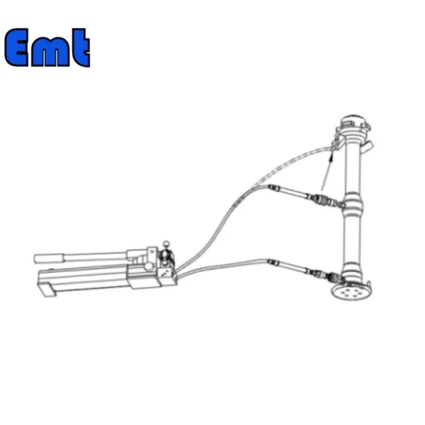
II. Pipelien Connection
Connect the high-pressure hydraulic hose to the hydraulic lifting tool and the manual hydraulic pump according to the hydraulic inlet and outlet marked on the hydraulic lifting tool and the manual hydraulic pump.
Note: Figure 2 (2) hydraulic inlet of hydraulic take-and-place tool, Figure 2 (3) hydraulic outlet of hydraulic take-and-place tool; Figure 3 (3) hydraulic pump inlet: Figure 3 (4) hydraulic pump outlet.
Ⅲ Check and prepare the hydraulic part of the manual hydraulic pump
1) Open the needle valve of the hydraulic lifting tool (4) in Figure 2;
2) Close the upper oil return valve of the manual hydraulic pump;
3) Open the refueling cover of the manual hydraulic pump so that the hydraulic pump is in a state of ventilation;
4) Push the upper reversing valve of the manual hydraulic pump to the installation position (7) in Figure 3, and start pumping pressure until the connecting rod of the hydraulic lifting tool in Figure 2 is exposed completely. If you feel that the pressure handle is elastic and the feedback force is small, it indicates that there is air in the pipeline. Repeat the operation of the pressure handle 3 to 6 times to exhaust the system air.
Ⅳ Inspection and treatment of hydraulic take-and-place tools
After the completion of step III, push the reversing valve on the manual hydraulic pump to the position of the reversing valve (6) in Figure 3, and start to press until the pressure gauge of the hydraulic pump shows 5MPa in Figure 3. Observe whether the connecting rod of the hydraulic lifting tool in Figure 2 retracts into the main cylinder at this time. If it retracts into the shell, it indicates that the hydraulic lifting tool works normally. Push the hydraulic pump direction valve to the middle position of the 7 reversing valve in Figure 3 and proceed to the next step; If the connecting rod in FIG. 2 cannot retract the housing, it means that the hydraulic lifting tool cannot work normally and needs to be sent to the manufacturer for maintenance. Push the direction valve of the hydraulic pump to the middle position of the reversing valve in FIG. 3 to relieve pressure, and send the hydraulic lifting tool to the manufacturer for maintenance.
V After the completion of operation and inspection, open the upper return valve of the manual hydraulic pump to relieve pressure, and then unscrew the high-pressure hydraulic hose joint on the hydraulic removal tool, and then unscrew high-pressure hydraulic hose joint on the hydraulic pump, and carefully coil up the high-pressure hydraulic hose.
Reviews
There are no reviews yet.