 English
 العربية
 Deutsch
 Bahasa Indonesia
 Português
 Русский
 Español
.11)")
Descripción
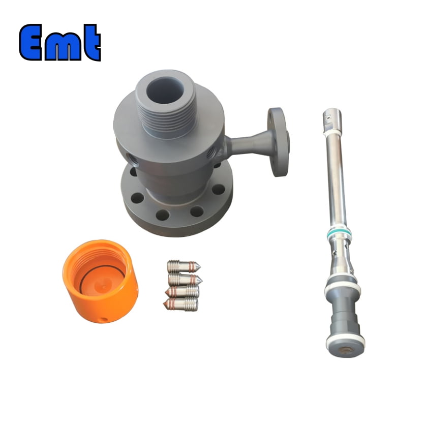
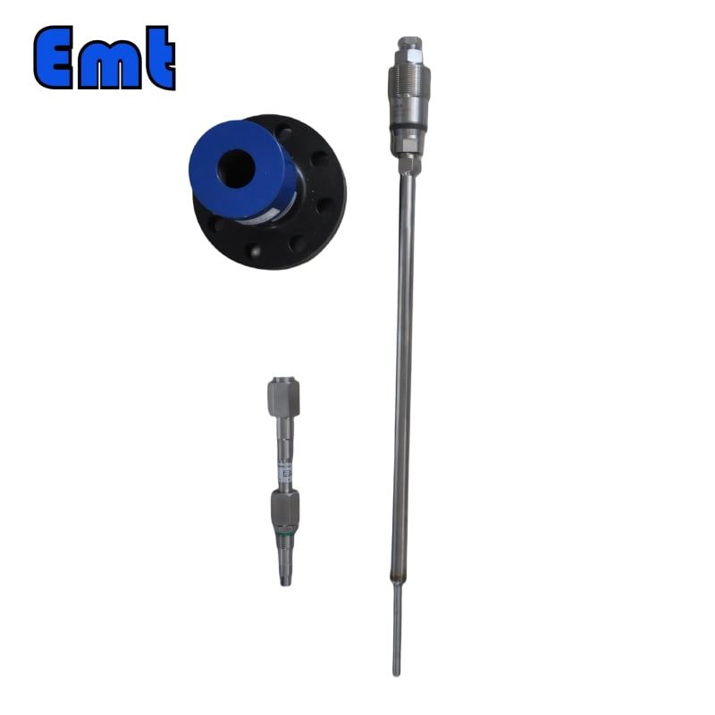
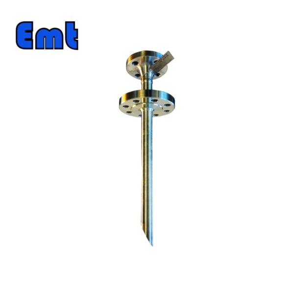
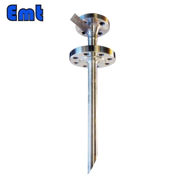
Una pluma de inyección de productos químicos es un dispositivo utilizado en diversas industrias, como la de petróleo y gas, para inyectar productos químicos en un sistema. Está diseñado para administrar productos químicos con precisión en un punto específico, lo que ayuda a controlar procesos o prevenir problemas como la corrosión en las tuberías. Estas plumas se pueden personalizar según las necesidades y están fabricadas con materiales de alta calidad para un uso confiable y duradero.
Las plumas de inyección se utilizan ampliamente en varios sectores debido a su capacidad para administrar productos químicos de forma precisa y segura a un sistema. En la industria del petróleo y el gas, se utilizan para inyectar inhibidores de corrosión en las tuberías para reducir la tasa de corrosión y extender la vida útil de la infraestructura. También se aplican en plantas de tratamiento de agua donde introducen desinfectantes para eliminar bacterias dañinas y otros patógenos. En la industria de fabricación de productos químicos, las púas de inyección se utilizan para agregar cantidades precisas de reactivos durante diferentes etapas de producción, garantizando la calidad y seguridad del producto. Por último, en las centrales eléctricas, ayudan en la inyección precisa de productos químicos para controlar el pH, prevenir la incrustación y reducir el potencial de corrosión en los sistemas de calderas.
| Nombre | High-Pressure Injection Quill | |
| Material | Stainless Steel 304, Stainless Steel 316, DSS F51, Carbon Steel A105N, and Inconel 625 | |
| Temperatura de funcionamiento | -20~+120℃ | |
| Características clave | easy to operate | |
| long life and high accuracy | ||
| low cost and high efficiency | ||
| Pago | TT/LC | |
| Ventajas | En primer lugar, son ligeros y flexibles. | |
| Secondly, excellent injection efficiency | ||
| Por fin, seguimiento preciso de la ubicación |
Metodo de instalacion
Follow these steps to install the chemical injection quill:
- Start by wrapping the sealing strip on the threaded end of the dropper. Attach this to the NPT fitting of the injection nut and tighten.
- Next, place the main seal packing on the plug’s screw with its larger end facing the plug’s center. Connect this to the other thread of the injection nut, tighten it, and secure the set screw.
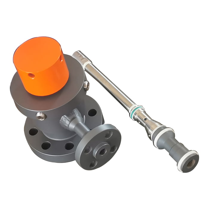
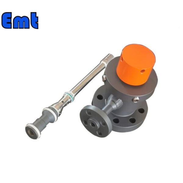
- Fije temporalmente el asiento de la brida del equipo a la brida de montaje de la tubería, pero no lo apriete todavía.
- Sujete firmemente el conjunto de inyección del tope ensamblado al asiento de la brida.
- Ahora, afloje la conexión a la brida de montaje. Retire todo el dispositivo y determine la orientación del bisel de la cánula de inyección. Ajuste la orientación de modo que la inclinación de la manga rociadora sea opuesta a la dirección del flujo del medio, opuesta a la boquilla. Puede medir o inspeccionar visualmente el ángulo entre el puerto en T o el adaptador de brida en T y la posición deseada.
- Desenrosque el cuerpo del conector de los conjuntos de inyección del tapón girándolo en sentido antihorario en un cierto ángulo. Luego afloje el tornillo de fijación de la tuerca de inyección y atorníllela.
- Si el cuerpo de inyección tiene forma de puerto en T, envuelva una tira selladora alrededor de los dos extremos del tubo NPT. Conecte un extremo a la abertura lateral tipo T en el pedestal de la brida y el otro al extremo de la válvula. Atorníllelos para asegurarlos.
| Modelo | ||||||||||||||||||||||||||||
| Y | Inyección de pluma SI | |||||||||||||||||||||||||||
| -Código | Enchufar | |||||||||||||||||||||||||||
| Pxxx | Tipo | Material | Material de sellado | |||||||||||||||||||||||||
| 0 | Sin solicitud | 0 | CS | 0 | Sin solicitud | |||||||||||||||||||||||
| 1 | Cuerpo de tapón hueco | 1 | 316SS | 3 | DSS | 1 | Junta tórica de Viton/empaquetadura primaria de PTFE | |||||||||||||||||||||
| 2 | Cuerpo de enchufe sólido | 2 | 316LSS | 4 | INCONEL | 2 | HNBR | |||||||||||||||||||||
| – Código | Tuerca de inyección | |||||||||||||||||||||||||||
| Nxx | Tamaño de conexión | Material | ||||||||||||||||||||||||||
| 0 | Sin solicitud | 0 | CS | |||||||||||||||||||||||||
| 1 | 1/4″ | 1 | 316SS | 3 | DSS | |||||||||||||||||||||||
| 2 | 1/2″ | 2 | 316LSS | 4 | INCONEL | |||||||||||||||||||||||
| – Código | Tubo de inyección | |||||||||||||||||||||||||||
| Sxxx-Lx″ | Tamaño de conexión | Material | Boquilla | Tamaño de línea(x″) | ||||||||||||||||||||||||
| 0 | Sin solicitud | 0 | CS | 0 | Sin solicitud | La posición más efectiva para la inyección es generalmente en el centro de la tubería. | ||||||||||||||||||||||
| 1 | 1/4″ | 1 | 316SS | 1 | Abierto | |||||||||||||||||||||||
| 2 | 1/2″ | 2 | 316LSS | 2 | Pluma | |||||||||||||||||||||||
| 3 | DSS | 3 | Cap & Core | |||||||||||||||||||||||||
| 4 | INCONEL | |||||||||||||||||||||||||||
| – Código | Niple y válvula (o brida final) de la T | |||||||||||||||||||||||||||
| txx | Tamaño de conexión | Material | ||||||||||||||||||||||||||
| 0 | Sin solicitud | 0 | CS | |||||||||||||||||||||||||
| 1 | Boquilla de 1/4″ | a | Boquilla y válvula de 1/4″ | 1 | 316SS | |||||||||||||||||||||||
| 2 | Pezón de 1/2″ | b | Boquilla y válvula de 1/2″ | 2 | 316LSS | |||||||||||||||||||||||
| 3 | Pezón de 3/4″ | C | Boquilla y válvula de 3/4″ | 3 | DSS | |||||||||||||||||||||||
| 4 | Pezón de 1″ | d | Boquilla y válvula de 1″ | 4 | INCONEL | |||||||||||||||||||||||
| 5 | Brida de 1/4″ | mi | Brida de extremo de pezón de 1/4 ″ | |||||||||||||||||||||||||
| 6 | Brida de 1/2″ | F | Brida de extremo de pezón de 1/2 ″ | |||||||||||||||||||||||||
| 7 | Brida de 3/4″ | gramo | Brida de extremo de pezón de 3/4 ″ | |||||||||||||||||||||||||
| 8 | Brida de 1″ | h | Brida del extremo del pezón de 1 ″ | |||||||||||||||||||||||||
| Por ejemplo:SI-P221-N12-S122-L4″-T22 SI: Conjunto de muestreo e inyección P221: Cuerpo del obturador sólido con junta tórica de Viton 316LSS y empaquetadura primaria de PTFE N12: Tamaño de conexión de tuerca de inyección: 1/4″ y Material: 316LSS S122: Inyección El tamaño de la conexión del tubo es 1/4 y el material es 316LSS. El tipo de boquilla es de púas. L4″:Para tubería de 4″. T22: Tamaño de conexión en T del niple: 1/2″, Material del niple: 316LSS | ||||||||||||||||||||||||||||
Reseñas
Aún no hay reseñas.