Descrição
Introdução
Overview of the importance of Chemical Injection in the O&G industry
Chemical injection plays a pivotal role in the Oil and Gas (O&G) industry, acting as a key catalyst in optimizing production efficiency and ensuring the longevity of key infrastructure. It’s used in various applications, from enhancing oil recovery in mature fields to mitigating corrosion, scale, and hydrate formation in pipelines and equipment. By injecting precise amounts of specific chemicals into the well or pipeline, operators can control the physical characteristics of the fluid, prevent the buildup of harmful substances, and maintain optimal conditions for O&G extraction and transportation. This not only boosts overall productivity but also reduces operational costs and extends the life of the infrastructure, making chemical injection an indispensable element of the O&G industry.
Entendendo a injeção química
Defining Chemical Injection within the O&G industry
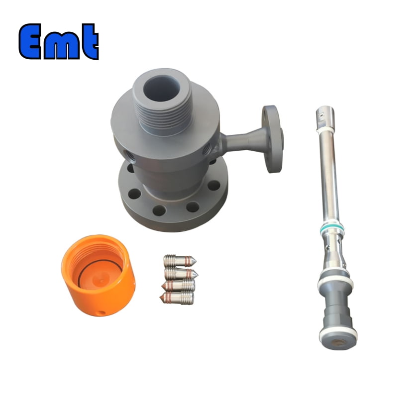
Chemical injection in the Oil and Gas (O&G) industry refers to the process of introducing specific chemicals into an operating system, such as a well or pipeline, to optimize production and maintain system integrity. This can involve injecting chemicals at the wellhead or downhole to manage fluid properties, prevent blockages, reduce corrosion, and facilitate the extraction and transportation of hydrocarbons. The chemicals used range from corrosion inhibitors, scale inhibitors, and biocides, to demulsifiers and surfactants, each serving a specific purpose. The injection rates and volumes are meticulously controlled depending on the operational needs, making chemical injection a precision-oriented and crucial part of O&G operations.
Examination of chemical introduction methods: Comparing wellhead and downhole injection
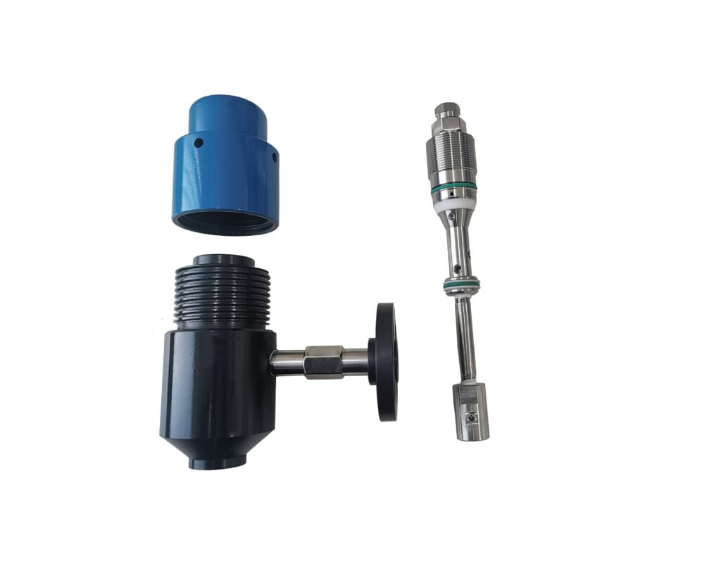
In the Oil and Gas (O&G) industry, chemical injection can be carried out at the wellhead or downhole, each method having its unique advantages. Wellhead injection involves introducing chemicals at the surface level of the well, which then travel down the wellbore along with the production fluids. This method is simpler and more economical but may not be as effective for deep or complex wells. On the other hand, downhole injection places chemicals closer to the reservoir, ensuring a more targeted application. This method can be more efficient in mitigating issues like scale or corrosion deep within the well. However, downhole injection is technically more complex and may require sophisticated equipment and monitoring systems. The choice between the wellhead and downhole injection primarily depends on the specific conditions and requirements of the well.
Chemical Injection in Produced Well Stream
Discussing the applications and benefits of chemical usage in the produced well stream
The use of chemicals in the produced well stream in the Oil and Gas (O&G) industry carries several benefits and applications. Chemicals such as corrosion inhibitors, scale inhibitors, and paraffin dispersants, among others, are added to manage the properties of the produced fluids and protect the infrastructure. For instance, corrosion inhibitors help protect the wellbore, production tubing, and surface equipment from corrosive elements present in the produced fluids, thereby prolonging the life of these assets. Scale inhibitors prevent the buildup of mineral scales, which can obstruct the flow path and decrease production efficiency. Paraffin dispersants help manage the wax content in crude oil, preventing blockages. These chemical applications not only optimize the flow of the well stream but also enhance the overall operational efficiency, making them an integral part of the O&G production process.
Chemical Injection in Enhanced Oil Recovery (EOR)
Elucidating Chemical Injection’s Role in EOR
Chemical injection plays a transformative role in Enhanced Oil Recovery (EOR), a technique used to extract additional oil from reservoirs beyond what’s possible with primary and secondary recovery methods. In the context of EOR, chemicals such as polymers, surfactants, and alkalis are injected into the reservoir to improve the displacement of oil and increase its mobility towards the production wells. Polymers increase the viscosity of the injected water, improving sweep efficiency. Surfactants reduce the interfacial tension between oil and water, enabling the displacement of trapped oil, while alkalis react with the oil to form soap-like substances, helping to mobilize immobile oil. The strategic use of these chemicals through injection can significantly boost oil recovery rates, making chemical injection a fundamental component of EOR strategies.
Advantages of Chemical Injection Quill in O&G
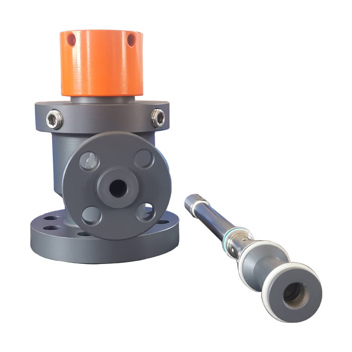
Chemical injection quills in the Oil and Gas (O&G) industry are instrumental in enhancing cost-effectiveness. They ensure that chemicals are evenly and directly introduced into the fluid flow, reducing the amount of chemicals needed for effective treatment, which cuts down on procurement and disposal costs. Moreover, these quills are designed to prevent process fluid backflow, which enhances operational safety and efficiency and further reduces chemical wastage. The preventative role of chemical injection quills in infrastructure maintenance cannot be overstated. They help minimize issues like corrosion and scaling in pipelines, thereby avoiding costly repairs or equipment replacements in the future.
Parâmetros Básicos
| Modelo | ||||||||||||||||||||||||||||
E | Encaixe de acesso para penas de injeção química | |||||||||||||||||||||||||||
| -Código | Plugue | |||||||||||||||||||||||||||
| Pxxx | Tipo | Material | Selagem Material | |||||||||||||||||||||||||
| 0 | Nenhum pedido | 0 | CS | 0 | Nenhum pedido | |||||||||||||||||||||||
| 1 | Oco Corpo do plugue | 1 | 316SS | 3 | DSS | 1 | Viton O-Ring / Embalagem primária de PTFE | |||||||||||||||||||||
| 2 | Corpo de plugue sólido | 2 | 316LSS | 4 | INCONEL | 2 | HNBR | |||||||||||||||||||||
| – Código | Porca de injeção | |||||||||||||||||||||||||||
| Nxx | Tamanho da conexão | Material | ||||||||||||||||||||||||||
| 0 | ou seja, sem solicitação | 0 | ou seja, CS | |||||||||||||||||||||||||
| 1 | ou seja 1/4″ | 1 | ou seja, 316SS | 3 | ou seja, DSS | |||||||||||||||||||||||
| 2 | ou seja 1/2″ | 2 | ou seja, 316LSS | 4 | ou seja, INCONEL | |||||||||||||||||||||||
| – Código | Injection Tube | |||||||||||||||||||||||||||
| Sxxx-Lx″ | Tamanho da conexão | Material | Bocal | Tamanho da linha (x″) | ||||||||||||||||||||||||
| 0 | Nenhum pedido | 0 | CS | 0 | ou seja, sem solicitação | A posição mais eficaz para injeção é geralmente no centro do tubo | ||||||||||||||||||||||
| 1 | ou seja 1/4″ | 1 | ou seja, 316SS | 1 | ou seja, aberto | |||||||||||||||||||||||
| 2 | ou seja 1/2″ | 2 | ou seja, 316LSS | 2 | ou seja, pena | |||||||||||||||||||||||
| 3 | ou seja, DSS | 3 | i.e. Cap & Core | |||||||||||||||||||||||||
| 4 | ou seja, INCONEL | |||||||||||||||||||||||||||
| – Código | Nipple and Valve(or end Flange)of the Tee | |||||||||||||||||||||||||||
| Txx | Tamanho da conexão | Material | ||||||||||||||||||||||||||
| 0 | ou seja, sem solicitação | 0 | ou seja, CS | |||||||||||||||||||||||||
| 1 | ou seja, 1/4 ″ Mamilo | a | ou seja, bico e válvula de 1/4 ″ | 1 | ou seja, 316SS | |||||||||||||||||||||||
| 2 | ou seja, 1/2 ″ Mamilo | b | ou seja, bico e válvula de 1/2 ″ | 2 | ou seja, 316LSS | |||||||||||||||||||||||
| 3 | ou seja, 3/4 ″ Mamilo | c | ou seja, bico e válvula de 3/4 ″ | 3 | ou seja, D SS | |||||||||||||||||||||||
| 4 | ou seja, 1 ″ Mamilo | d | ou seja, 1 ″ Mamilo e Válvula | 4 | ou seja, INCONEL | |||||||||||||||||||||||
| 5 | ou seja, flange de 1/4 ″ | e | ou seja, flange de extremidade de bico de 1/4 ″ | |||||||||||||||||||||||||
| 6 | ou seja, flange de 1/2 ″ | f | ou seja, flange de extremidade de bico de 1/2 ″ | |||||||||||||||||||||||||
| 7 | ou seja, flange de 3/4 ″ | g | ou seja, flange de extremidade de bico de 3/4 ″ | |||||||||||||||||||||||||
| 8 | ou seja, 1″Flange | h | ou seja, 1 ″ Flange da extremidade do bico | |||||||||||||||||||||||||
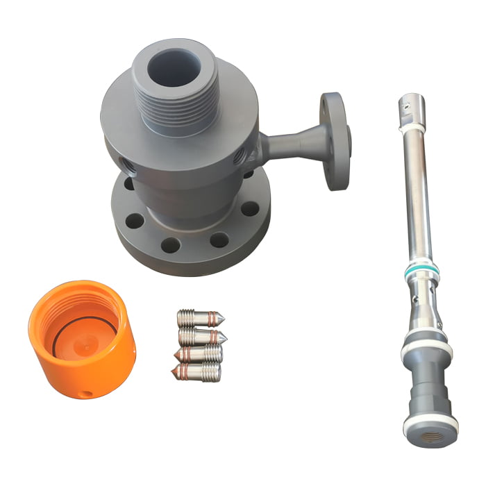
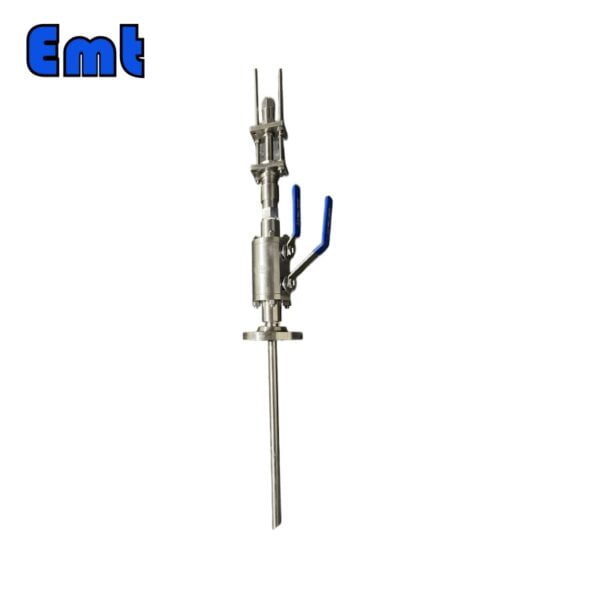
| Por exemplo, Si-P221-N12-S122-L4 ″ -t22 SI:e.g. Sampling & Injection Assembly, P221: e.g. Solid Plug Body in 316LSS Viton O-Ring and PTFE Primary Packing, N12:e.g. injection Nut Connection Size is 1/4″and Material is 316LSS, S122:e.g. injection Tube Connection Size is 1/4″ and Material is 316LSS.The type of nozzle is quills L4″:Para tubo de 4″. T22: Nipple of Tee Connection Size is 1/2″, Nipple material is 316LSS | ||||||||||||||||||||||||||||
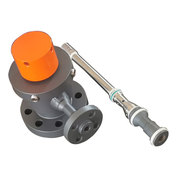
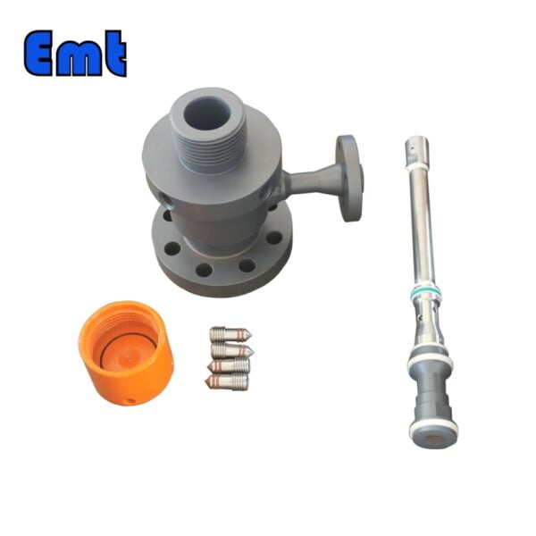
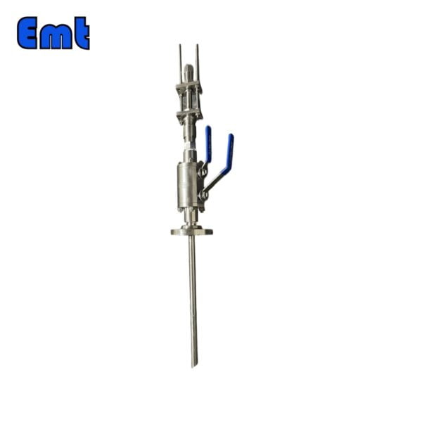
Nome | Encaixe de acesso para penas de injeção química | |
| Material | Aço Inoxidável 304, Aço Inoxidável 316, DSS F51, Aço Carbono A105N e também Inconel 625 | |
| Temperatura de operação | -20±120 | |
| Recurso | Em primeiro lugar, operação fácil | |
| Em segundo lugar, alta precisão e longa vida | ||
| Lastly, high Efficiency, Low cost | ||
| Pagamento | TT/LC | |
| Vantagem | Em primeiro lugar, são leves e flexíveis. | |
| Em segundo lugar, excelente eficiência de injeção. | ||
| Finalmente, rastreamento de localização preciso.V |
Conclusão
In conclusion, chemical injection is an integral part of the Oil and Gas (O&G) industry, serving a range of critical functions from optimizing well streams to enhancing oil recovery. By precisely controlling the introduction of chemicals, operators can manage fluid properties, prevent blockages, reduce corrosion, and facilitate efficient hydrocarbon extraction and transportation. The use of chemical injection quills further bolsters this process, ensuring even distribution of chemicals, preventing backflow, and contributing to infrastructure maintenance. Therefore, the strategic employment of chemical injection and the use of effective injection methods such as quills can significantly boost operational efficiency, extend the lifespan of key infrastructure, and result in substantial cost savings, reinforcing the indispensable nature of this technique in the O&G industry.

Avaliações
Não há comentários ainda.