Description
Chemical injection quills are crucial for precise chemical delivery and dispersion within industrial systems. These devices integrate chemicals into main flow streams, ensuring even distribution and preventing pipeline damage.
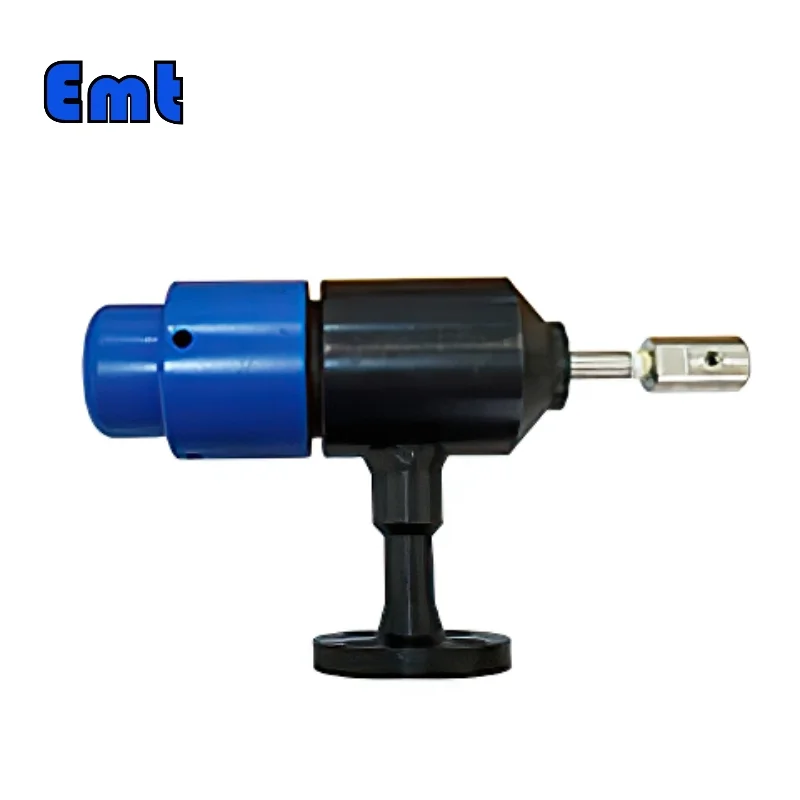
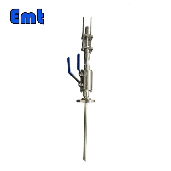
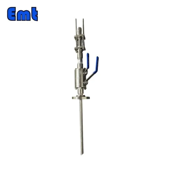
Chemical injection quills inject chemicals directly into pressurized pipelines, tanks, or vessels. They extend into the flow stream, ideally near the center, for optimal mixing. The main purpose of the quill is to achieve a homogeneous mix of chemicals with process fluids, essential for effective chemical reactions and preventing corrosion or inefficiency.
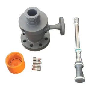
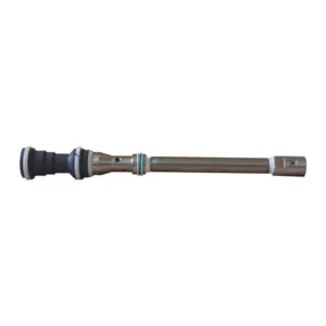
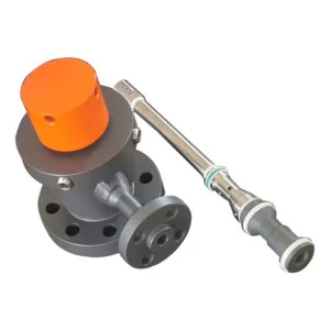
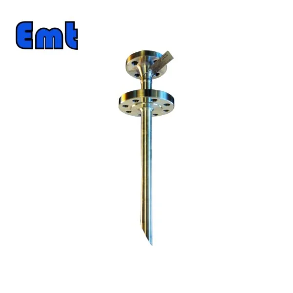
The design of a chemical injection quill typically features a long, narrow tube. One end connects to a chemical feed line, and the other extends into the main pipeline or tank. The tip includes one or more nozzles or ports for injecting chemicals into the flow. This strategic placement prevents chemicals from sticking to container or pipeline walls, ensuring even distribution and minimizing potential damage.
Applications Across Industries
Chemical injection quills are widely used across various industries for their effectiveness in managing chemical dispersion. In the oil and gas industry, they inject corrosion inhibitors, scale inhibitors, or biocides into pipelines and tanks. This helps protect against corrosion and scale buildup, maintaining flow and efficiency. In power plants, these quills are essential for adding chemicals to boiler water to prevent scaling and corrosion. Marine and desalination plants use these quills to inject anti-scaling chemicals into seawater before desalination, enhancing the process’s longevity and efficiency.
By ensuring precise and even chemical distribution, chemical injection quills maintain the efficiency, safety, and longevity of industrial operations across these sectors. Their role in preventing damage and ensuring effective chemical reactions makes them indispensable in modern industrial applications.
Selection Model
| Model | |||||||||||||||||||||||||||
| SI | Chemical Injector Quill | ||||||||||||||||||||||||||
| -Code | Plug | ||||||||||||||||||||||||||
| Pxxx | Type | Material | Sealing Material | ||||||||||||||||||||||||
| 0 | No Request | 0 | CS | 0 | No Request | ||||||||||||||||||||||
| 1 | Hollow Plug Body | 1 | 316SS | 3 | DSS | 1 | Viton O-Ring / PTFE Primary Packing | ||||||||||||||||||||
| 2 | Solid Plug Body | 2 | 316LSS | 4 | INCONEL | 2 | HNBR | ||||||||||||||||||||
| – Code | Injection Nut | ||||||||||||||||||||||||||
| Nxx | Connection Size | Material | |||||||||||||||||||||||||
| 0 | i.e. No Request | 0 | i.e. CS | ||||||||||||||||||||||||
| 1 | i.e. 1/4″ | 1 | i.e. 316SS | 3 | i.e. DSS | ||||||||||||||||||||||
| 2 | i.e. 1/2″ | 2 | i.e. 316LSS | 4 | i.e. INCONEL | ||||||||||||||||||||||
| – Code | Injection Tube | ||||||||||||||||||||||||||
| Sxxx-Lx″ | Connection Size | Material | Nozzle | Line size(x″) | |||||||||||||||||||||||
| 0 | No Request | 0 | CS | 0 | i.e. No Request | The most effective position for injection is generally at the center of the pipe | |||||||||||||||||||||
| 1 | i.e. 1/4″ | 1 | i.e. 316SS | 1 | i.e. Open | ||||||||||||||||||||||
| 2 | i.e. 1/2″ | 2 | i.e. 316LSS | 2 | i.e. Quill | ||||||||||||||||||||||
| 3 | i.e. DSS | 3 | i.e. Cap & Core | ||||||||||||||||||||||||
| 4 | i.e. INCONEL | ||||||||||||||||||||||||||
| – Code | Nipple and Valve(or end Flange)of Tee | ||||||||||||||||||||||||||
| Txx | Connection Size | Material | |||||||||||||||||||||||||
| 0 | i.e. No Request | 0 | i.e. CS | ||||||||||||||||||||||||
| 1 | i.e. 1/4″Nipple | a | i.e. 1/4″Nipple and Valve | 1 | i.e. 316SS | ||||||||||||||||||||||
| 2 | i.e. 1/2″Nipple | b | i.e. 1/2″Nipple and Valve | 2 | i.e. 316LSS | ||||||||||||||||||||||
| 3 | i.e. 3/4″Nipple | c | i.e. 3/4″Nipple and Valve | 3 | i.e. D SS | ||||||||||||||||||||||
| 4 | i.e. 1″Nipple | d | i.e. 1″Nipple and Valve | 4 | i.e. INCONEL | ||||||||||||||||||||||
| 5 | i.e. 1/4″Flange | e | i.e. 1/4″Nipple end Flange | ||||||||||||||||||||||||
| 6 | i.e. 1/2″Flange | f | i.e. 1/2″Nipple end Flange | ||||||||||||||||||||||||
| 7 | i.e. 3/4″Flange | g | i.e. 3/4″Nipple end Flange | ||||||||||||||||||||||||
| 8 | i.e. 1″Flange | h | i.e. 1″Nipple end Flange | ||||||||||||||||||||||||
| For Example, SI-P221-N12-S122-L4″-T22 | |||||||||||||||||||||||||||
Benefits of Using Chemical Injection Quill:
The use of chemical injection needles has a double advantage. First, they provide a safe and effective means of connecting liquid chemical feedstocks to pipes or containers, reducing the risks associated with corrosive, flammable or hazardous substances. Second, these spines improve the efficiency of the chemical feed system by ensuring the uniform dispersion and optimal mixing of chemicals in the pipeline.
Flow Direction and Mounting Types:
When installing an injection tube in a liquid stream, the end of the 45 degree Angle should face downstream. For larger pipes, the end of the quill should be placed at the midstream or at least 2 inches from the bottom of the pipe. The injection tubes are available in different mounting options, including 2 “flanges, 2” welded joints, and 1 “NPT welded base. These changes are adapted to the specific installation requirements of different industries.
Materials of Construction for Injection Quills:
Injection quills are manufactured using various materials, including Inconel 825, Inconel 625, Hastelloy, Monel, Stainless Steel, and Forged carbon steel. These materials are selected for their chemical resistance and durability, ensuring the quills can withstand the corrosive nature of the process fluids they come into contact with.
Types of Chemical Injection Quills:
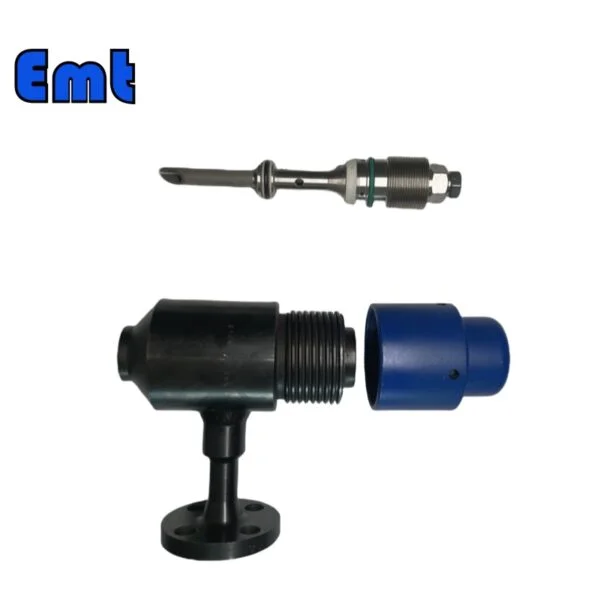
There are two main types of chemical injection quills: retractable and non-retractable. Both types serve the same purpose, but the retractable quill offers the added advantage of being easy to retract for easy maintenance. The retractable quill allows the maintenance team to clean and clean the quill, ensuring its continued effectiveness. Regular maintenance is essential because handling chemicals can form deposits that may eventually clog the feather tube. Removing these deposits is essential for the quill to perform its function effectively.
Maintenance
To maintain optimum performance, chemical injection quills must be regularly maintained and cleaned. Deposits from handling chemicals, such as sodium hypochlorite, ammonia, and polymers, can build up over time, leading to blockages. Just like cleaning toilets on a small scale, maintenance teams have to clean these deposits regularly to make sure the quills are working effectively.

Reviews
There are no reviews yet.