Beschreibung
Schweißschweiner -Signalerübersicht
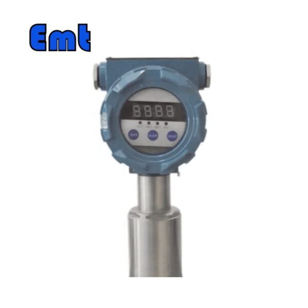
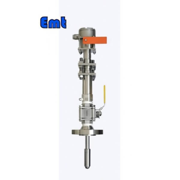
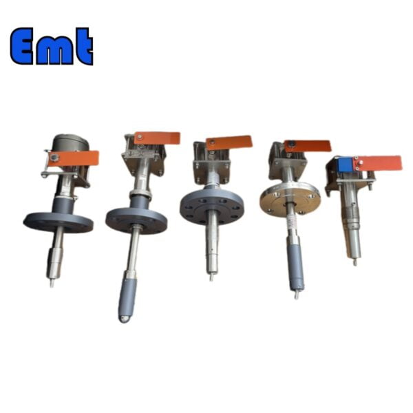
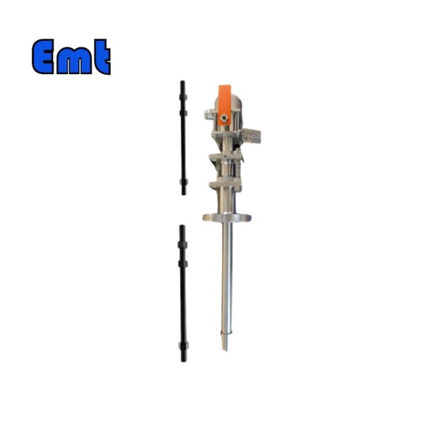
Der Schweißschweiner -Signaler wird zum Schweinern der Öl-, Gas-, Wasser- und anderen Getriebepipelines verwendet, und der Schweißschweinelement ist ein gemahlenes Richtinstrument, unabhängig davon, ob das Schwein vorbeikommt oder nicht. Es ist nicht nur einfach zu installieren, sondern kann auch die Anforderungen verschiedener Pipelines für Indikatoren erfüllen. Das englische Betriebssystem ist die Interaktion zwischen Mensch und Computer bequem und intuitiv. Beim Testen müssen Sie den Indikator nur an die Pipeline anscheiben, um zu arbeiten.
Der Schweißschweiner -Signaler ist ein notwendiges Gerät für den Reinigungsvorgang in der Pipeline. Es hat viele Vorteile: Erstens ist die Struktur einfach. Zweitens sind die Anweisungen intuitiv. Drittens können Zuverlässigkeit, niedrige Kosten usw. auch elektrische Kontakte hinzugefügt werden, und es können Signale remote übertragen werden, um mehrere Anzeigen von Schall, Licht und Strom zu erreichen.
Die Basis des Schweißschweinenssignals ist auf dem Rohr geschweißt und sein Stürmer wird in das Rohr eingefügt. Wenn das Rohrschwein durchgeht, wird der Stürmer berührt und die rotierende Welle und die auf der Schacht installierte Anzeigeplatte werden abgeladen, was visuell zeigen kann, dass das Rohrschwein den Ort überschritten hat, und dann auf manuelles Zurücksetzen der Indikatorplatte und des Pendelhebels. Um Fehleinschätzungen zu vermeiden, ist es normalerweise nicht so konzipiert, dass sie automatisch zurückgesetzt werden. Zusätzlich zum Erreichen der Druckfestigkeit besteht der Indikator hauptsächlich darin, die Anforderungen der Verhinderung von Korrosion, der Gewährleistung der Versiegelung und der Verhinderung von Leckagen zu erfüllen.
Aus diesem Grund bestehen alle rotierenden Teile mit Flüssigkeit aus Edelstahl und korrosionsbeständigen Materialien. Der Hauptkörper und die rotierende Welle sind mit zwei Gummi -Ringen versiegelt, der obere Schraubenstopfen ist mit Gummiringen versiegelt und der Hauptkörper und die Basis sind mit Gummiklingen versiegelt. Der Versiegelungsring muss geschützt werden, da dies die einzige Möglichkeit ist, gegen Leckagen zu garantieren. Um sich an verschiedene Rohrdurchmesser und Kugeldurchmesser anzupassen, muss die Installationsbogenfläche der Indikatorbasis und die Länge der Schwungstange entsprechend eingestellt werden.
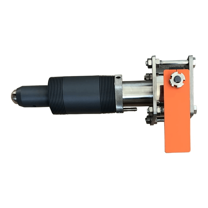
Die Grundstruktur des Schweißschweinenssignals (siehe angehängtes Bild),
Der Indikator besteht hauptsächlich aus einem mechanischen Körper und einem Anzeigemechanismus
- Auslöser: Es kann in beide Richtungen gedreht werden.
- Schraubenstopfen: Siehe den Standard -2 -Zoll -Stecker, der den Installationsbedingungen unter Druck entspricht.
- Basis: Kohlenstoffstahl, Legierungsstahl oder 304 Edelstahl mit guter Schweißleistung.
- Dichtungsring.
- Stößel.
- Dichtungsring.
- Frühling.
- Stop -Waschmaschine (Stoppschraube).
- Erhöhen Sie den Stift -Stecker.
- Hebelsystem.
- Oberkörper.
- Stößel.
- Ziehen Sie die Schrauben fest.
- Inner Touch -Stange: Drücken Sie ihn, um den Taktregelkopf zu stoppen: Das mechanische Anzeigenzeichen kann aufstehen, die Zeit zum digitalen Display und die Fernübertragung.
- Anzeigemechanismus: Gemäß den Bedürfnissen der Benutzer kann der Taktregelkopf und der mechanische Indikatormechanismus mit explosionssicherem Digital installiert werden
Anzeige oder Strom, Licht, Schall und andere Signalquellen.
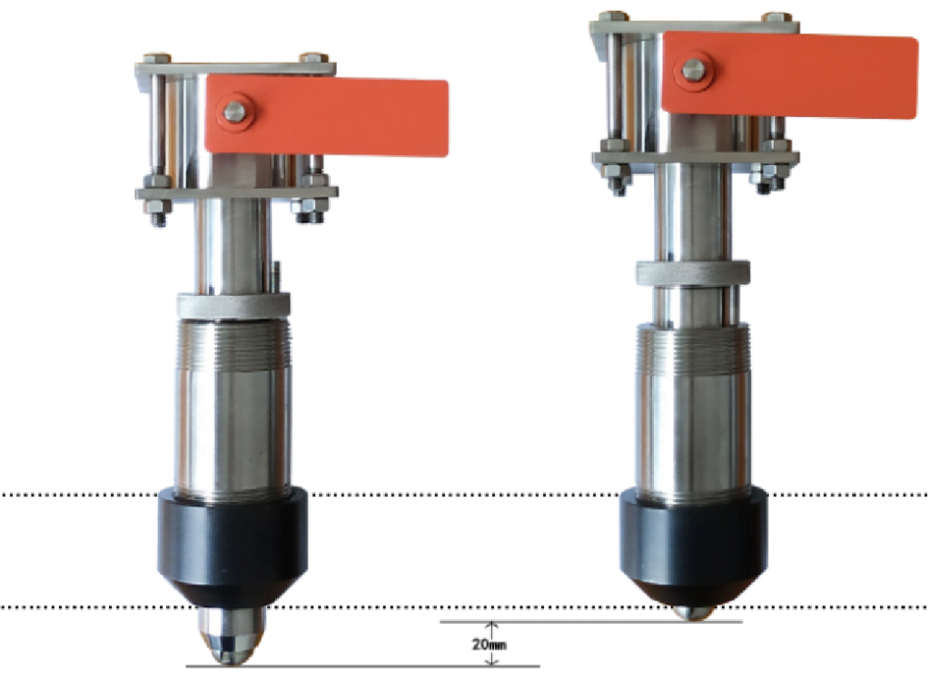
Installationsmethode für Schweißschweineherde:
- Überprüfen Sie vor der Installation, ob der mechanische Körper- und Anzeigemechanismus des Indikators flexibel und zuverlässig ist, und befolgen Sie dann die Struktur- und Installationsanweisungen.
Es soll den Hauptkörper der Maschine zerlegen und die Basis und die Pipeline separat anscheißen.
- Schweißbasis:
- No-Pressure-Installation: Entfernen Sie die Installationsstelle, entfernen Sie alle Anhänge und legen Sie die wahre Farbe des Metalls frei.
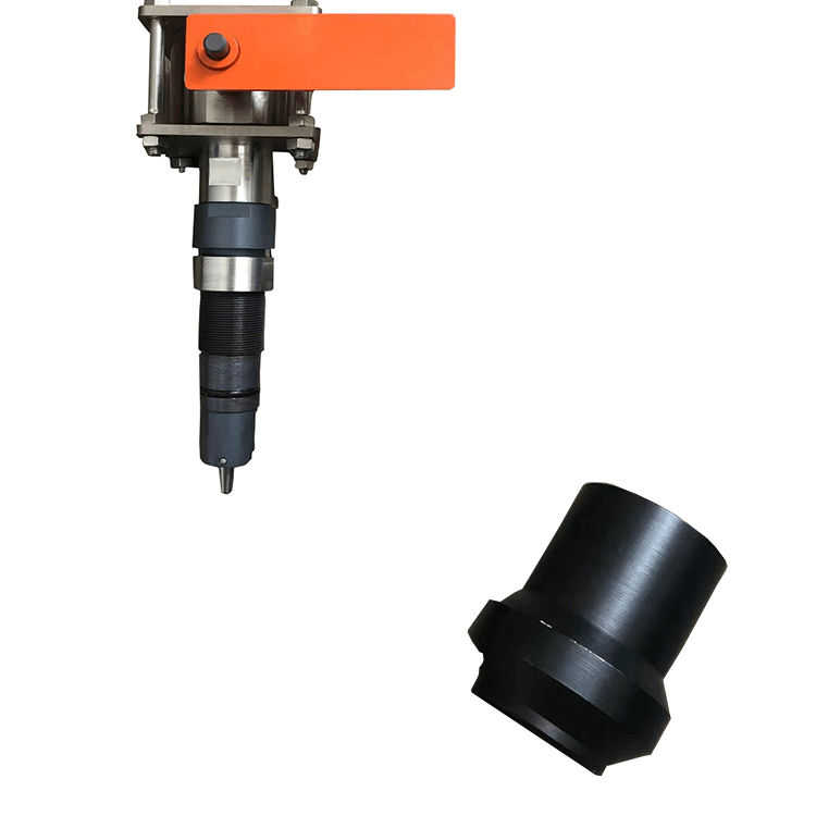
Richten Sie die Basis (Schweißausrichtungdiagramm) so aus, dass die Schlitzrichtung am oberen Ende der Basis parallel zur Mittellinie der Pipeline oder die Marke am oberen Ende der Basis an der Mittellinie der Rohrleitung (die Schlitzrichtung oder Marke an der Basis mit der Bewegungsrichtung des Auslösers) liegt. Komprimieren Sie die Basis, um sich während des Schweißens zu verhindern. B. Installation unter Druck: (Siehe Bedienungsanleitung der Bohrmaschine). Hinweis: Beim Schweißen der Basis auf der Pipeline sollte der Druck P in der Pipeline begrenzt sein.
Berechnungsformel: 2δs (T-C) 0,72 kgf/cm2
ΔS; die Ertragsgrenze des Materials.
T: Pipeline Wandstärke MM
C: zusätzliche Wandstärke (Negative Abweichung, Korrosionszulage usw.) dauert im Allgemeinen 1,5-2 mm.
D: Pipeline Außendurchmesser mm.
C: Nach Abschluss des Schweißens und Installation des Hauptteils der Maschine gemäß dem Struktur- und Installationsdiagramm die
Der mechanische Hauptkörper ist in Sequenz installiert, und der Anzeigemechanismus ist mit Befestigungsschrauben gemäß dem Struktur- und Installationsdiagramm verbunden, und die Richtung des Anzeigemechanismus kann für eine einfache Beobachtung eingestellt werden.
Warum brauchst du einen Schweißschweiner -Signaler?
Eine regelmäßige Reinigung von Rohren kann die Transporteffizienz verbessern.
Der Schweinesignaler hilft Ihnen, zu bestätigen, dass das Schwein vergangen ist.

Basismerkmal oder Parameter der Schweißschweineherde -Signaler -Pipeline | ||||
| Pig Detector Pipeline | B | C | D | |
| Typ | Intrusive | |||
| Anzeigefunktion | Manuelles Reset-Flag | Manuelles Reset-Flag kombiniert mit elektrischen Signalen | Date and time display combined with electrical signals | |
| Installing type | 2″Flange. As per ASME B16.5 (CLASS150~2500) | |||
| Plug body length _Correspond to the total standoff | 200mm/Meet the actual needs | |||
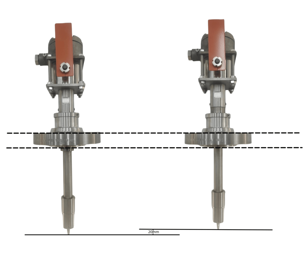
| Insert depth adjustment | 20mm | |||
| Operating temperature | -20~120℃/Meet customer requirements | |||
| NACE MR 0175 | Ja | |||
| Ingress protection | IP66 | |||
| Explosion-proof class | ExdⅡ BT4 | ExdⅡ BT4 | ||
| Remove under pressure | Nein | |||
| Optionale Funktion | ||||
| ● Standardkonfiguration ○ Optionale Konfiguration – Keine | ||||
| Triggertyp (B-bidirektional/U-unidirektional*) | ●/○ | |||
| Innenteilmaterial (Edelstahl 316L/DSS/INCONEL) | ●/○/○ | |||
| Flansch-/Gehäusematerial (PTFE-beschichtetes A105N/304SS/316LSS/DSS/INCONEL /Gemäß MR) | ●/○/○/○/○/○ | |||
| The position of the Internal liquid surface (High_Need to heating/Low_With no need for heating) [Only uni-directional pig detectors] | ●/○ | |||
| Material der Anschlussdose (Aluminiumlegierung/316SS) | —/— | ○/● | ●/— | |
| Schaltertyp (DPDT/2*SPDT) | —/— | ○/● | ○/● | |
| Schaltbewertung (DC24V 3A/DC24V 5A) | —/— | ●/○ | ●/— | |
| Elektrische Anschlussgröße (M20×1,5(F)/1/2″NPT(F)) | —/— | ●/○ | ●/— | |
| * Standard configuration of Uni-directional trigger is ball shape. | ||||
| Corresponding relations between the trigger and Insert depth (In pipe) | ||||
| Triggertyp | Bidirektional | Unidirektional | ||
| Einstecktiefe (im Rohr) | 21mm | 13mm | ||
Pipeline Welding Process
Qualität ist der Kerngehalt des Öl- und Gaspipeline -Baumanagements, daher wird eine Reihe von Arbeiten in Bezug auf Qualität durchgeführt. In der Praxis wird der Schwerpunkt auf der Kontrolle der Qualität des Pipeline -Schweißvorgangs gelegt. Beginnen Sie mit dem Schweißprozess, machen Sie im gesamten Prozess der Schweißqualitätskontrolle gute Arbeit. Stärken Sie die Kontrolle von Materialien, Personal und anderen Faktoren, um die Sicherheit und Qualität der Pipeline -Verwendung in der späteren Phase zu gewährleisten. 1. PETROCHEMISCHER PIPELE -Schweißprozess
Derzeit sind die Hauptschweißprozesse petrochemischer Pipelines 😀 Bogenschweißen. Im Pipeline -Schweißbetrieb nimmt der Schweißboden Lichtbogenschweißen an, wodurch der Schweißeffekt gewährleistet ist. Gemäß den verschiedenen Elektroden kann das Lichtbogenschweißen in Schmelzschweißen und nicht melkte polare Fluor-Bogenschweißen 2 Kohlendioxidgasschweißen unterteilt werden. In praktischen Anwendungen ist es erforderlich, die Schweißposition und die technischen Anforderungen zu klären. Vor dem Schweißen sollte die Rille gereinigt werden und die Öl- und Lackschicht auf der Oberfläche beider Seiten gereinigt werden. Darüber hinaus sollten Geräte- und Luftrouten überprüft werden. Das Kohlendioxidgasabschweißprozess übernimmt normalerweise die Desoxidation von SI und MN, und der Schweißeffekt ist besser. Füllstoff für Elektrodenbogenschweißen.
Generally speaking, in the petrochemical pipeline welding operation, after the bottom welding operation is completed, the slag and other impurities generated by the welding operation should be cleaned up in time. If a hidden problem is found, remove it, weld it, and ground it again. When filling with electrode arc welding, it is necessary to ensure that the position of the bottom weld and the weld is staggered by more than 10mm, and the electrode with a diameter parameter of 3.2mm is used in the middle position. If the pipe wall thickness parameter is 9mm, the welding rod is set at the middle seam of the three-layer weld, and the diameter parameter is 3~5mm.


Rezensionen
Es gibt noch keine Bewertungen.